

In this workshop, we will design an Arduino Nano-compatible microcontroller board using KiCAD.
A finished SparkleTilt looks something like this (with your design customizations, of course):
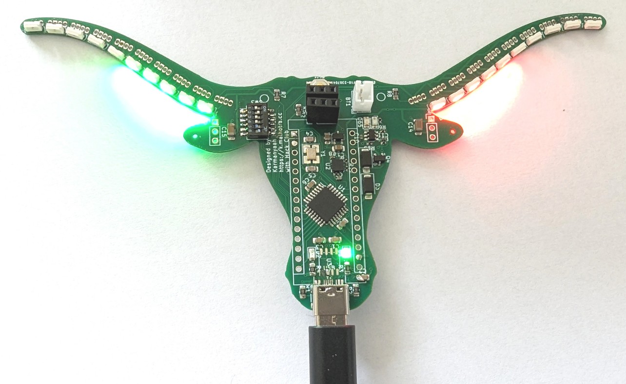
Video Demo
Prerequisites
If you are not already familiar with the basics of using an ECAD tool like EasyEDA or KiCAD, check out @maggie's workshop on designing a PCB Business card in EasyEDA:This video demonstrates the basics of navigating around KiCAD.
In addition, the rest of the workshop assumes you know basic electronics terms like:
- Resistor: A resistor limits the electric current that flows through a circuit. Resistance is the restriction of current.
- Capacitor: A capacitor stores charge, and thus energy. It's like a tiny battery that charges and discharges very quickly.
- Diode: A diode only allows current to flow in one direction. It also drops a little bit of voltage, turning that energy into heat.
- Microcontroller: A microcontroller (aka MCU) is a system on a chip that contains an integrated processor, memory, and input/output peripherals, which are used to interact with other electronic components.
Part Selection
Step 0 of designing a board is to clearly define what problem you need the board to solve. Here, we are making a nice looking level. The primary goal is to demonstrate electronics and PCB concepts. A secondary goal is to have an attractive and fun level.
Step 1 of designing a board is selecting your core components:
-
Microcontroller: ATmega328P. The ATmega series is the most robust and common 8-bit MCUs, being used in many Arduinos since the beginning. Additionally, it requires very few external components and runs over a wide range of voltages (1.8V-5.5V). It's also one of the very few microcontrollers that is a Basic Part on JLCPCB. And, it's available in a QFP package so it can be hand-soldered. It doesn't have many fancy features, but it's simple and robust.
-
USB-Serial Interface: CH340N. Because the ATmega328P doesn't have a built-in USB interface, we need a USB-UART IC. @hugo said that the CH340C worked well for him, and it's very cheap, so I'm using it too. The CH340N is the cheapest IC from the CH340 series that has an integrated clock, meaning fewer components are needed.
-
Pinout: While not technically a component, we will follow the standard Arduino Nano pinout. This really doesn't matter— unless you value your future self's sanity when trying to wire up new components.
Now on to the actual circuit. Make sure you have KiCAD downloaded, then set up a new project, and open the schematic editor.
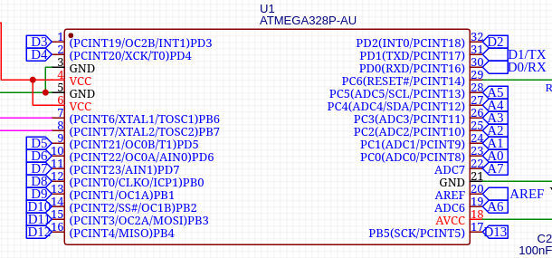
Core (Microcontroller)
First, we place the heart of our system, the ATmega328P-AU, in a TQFP package. This is NOT the ATmega328PB, which is not backward compatible with the ATmega328P.
Power
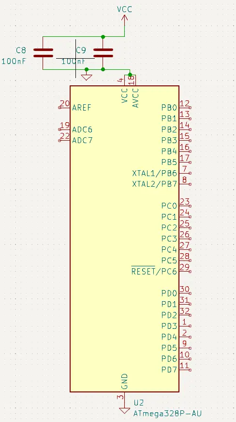
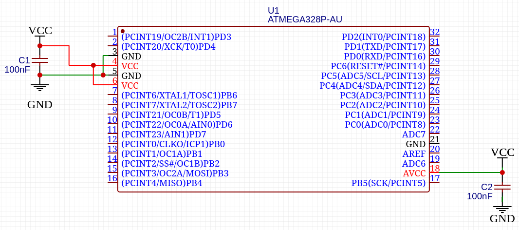
Then, we need to connect the power pins to power nets and place decoupling capacitors.
Nets: Nets like VCC and GND serve as abstractions for actual connections in our schematic. If we connected every single chip to a central VCC and GND point in our schematic, it would be very messy. These symbols tell the PCB Designer that we need to connect those pins while keeping the schematic clean.
Decoupling Capacitors: A decoupling capacitor is placed very close to the chip that needs or supplies power. When a chip suddenly demands power, it provides it while the battery and other components ramp up. It also absorbs noise and voltage spikes from the power source. So, these have to be as close to their parent IC as possible.
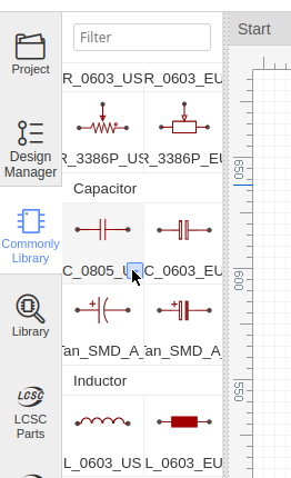
For the capacitors, go to "Common Library", click the arrow next to C_0603_US and select C_0805_US (sizes will be explained later).
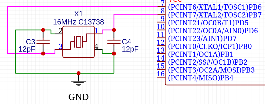
Clock
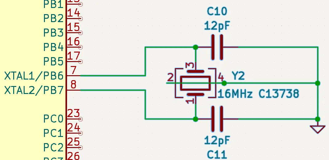 The datasheet for our crystal, C13738, shows that pins 2 and 4 are connected to ground. So, import the part "Crystal_GND24".
 Search for "C13738" in the Library for the clock.
Now that our MCU is powered, it needs a clock to tick to. We can configure the ATmega328P to use this 16MHz crystal rather than run at its default of 1MHz.
This crystal needs an accompanying capacitor connected to ground on each pin.
How did I come up with the value of these capacitors?
C = 2 * CL - CS
Here, C is the capacitor we need, CL is the load capacitance specified by the crystal manufacturer, and CS is the stray capacitance of the microcontroller pin. In our case CL (of the crystal) is 9pF and CS (of XTAL1/2) is 6pF (as specified by the datasheet).
So, we use 12pF capacitors.
Reset
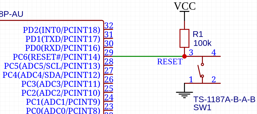 Search for
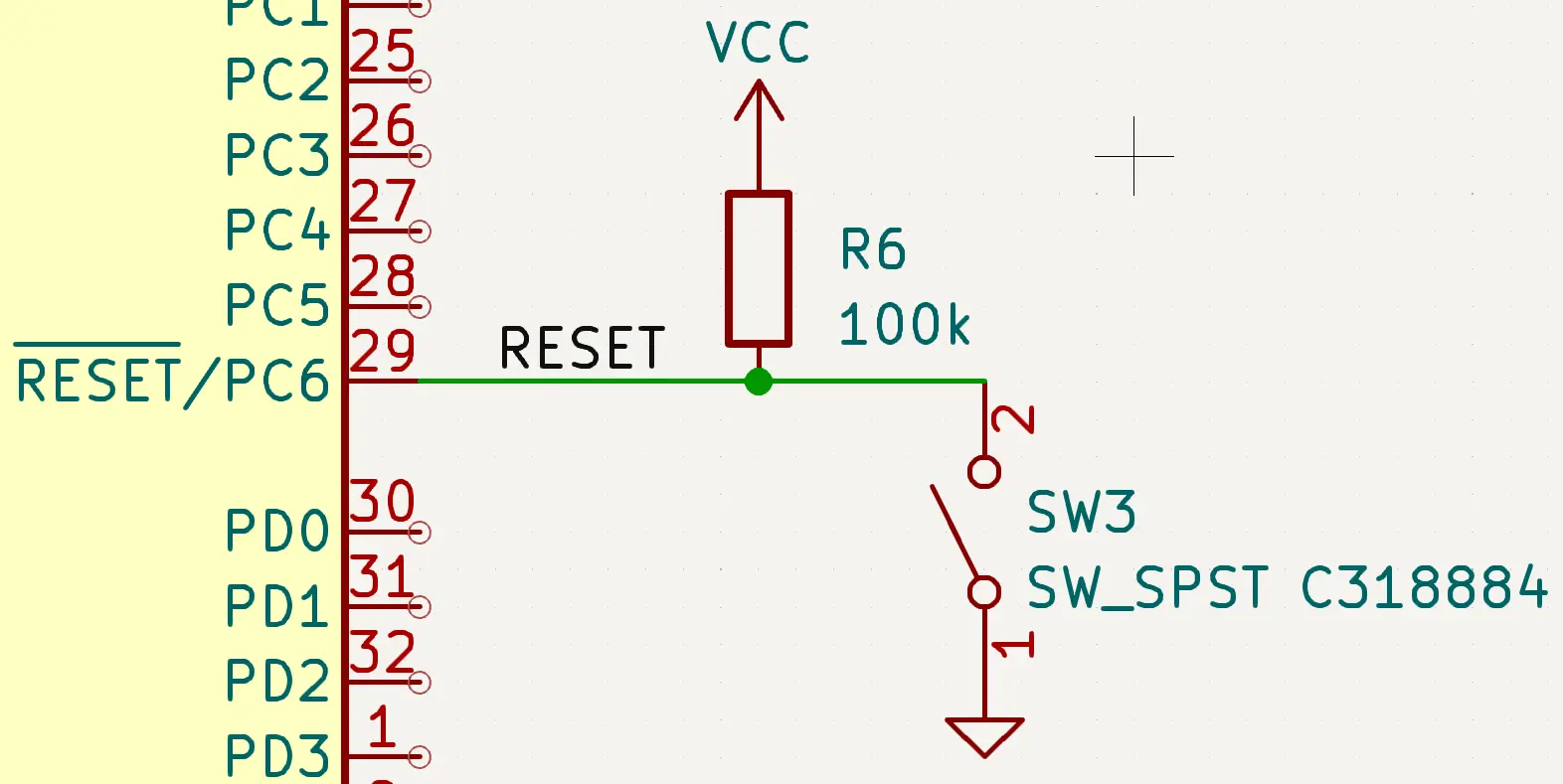
 C318884 in the library to find the switch. Just like the capacitor, use a R_0805_EU resistor.
The bar or hash next to RESET means that it is active low, 0V will reset the MCU and it should be at 5V during normal operation. The SPST button here is JLCPCB's basic push button which connects RESET to ground when pressed.
The resistor R6 is a pull-up resistor, a high-resistance resistor that gently pulls the RESET pin HIGH without passing too much current through it. This allows the switch to pull the RESET pin down without causing a short circuit, while preventing random noise from pulling RESET down.

Use the Net Label tool to label that line RESET.
Labeling this wire as RESET connects it to the RESET net. If we place another RESET label somewhere else on this page, our ECAD tool will understand that these two points have to be connected, just like the GND and VCC nets.
Label Pinout
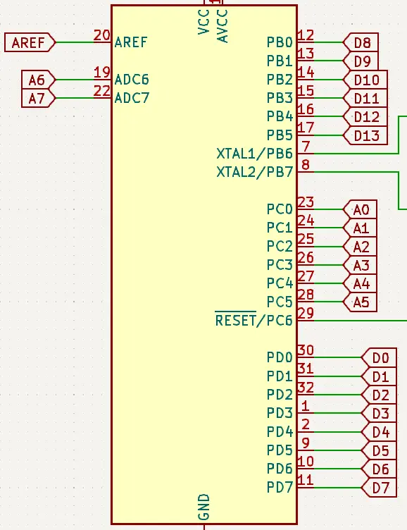
After this, we need labels telling us which MCU pin is which Arduino Nano pin.
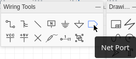
Use the Net Port tool for this.
These are global labels. Unlike the RESET label, these work on all pages of the schematic.
Headers
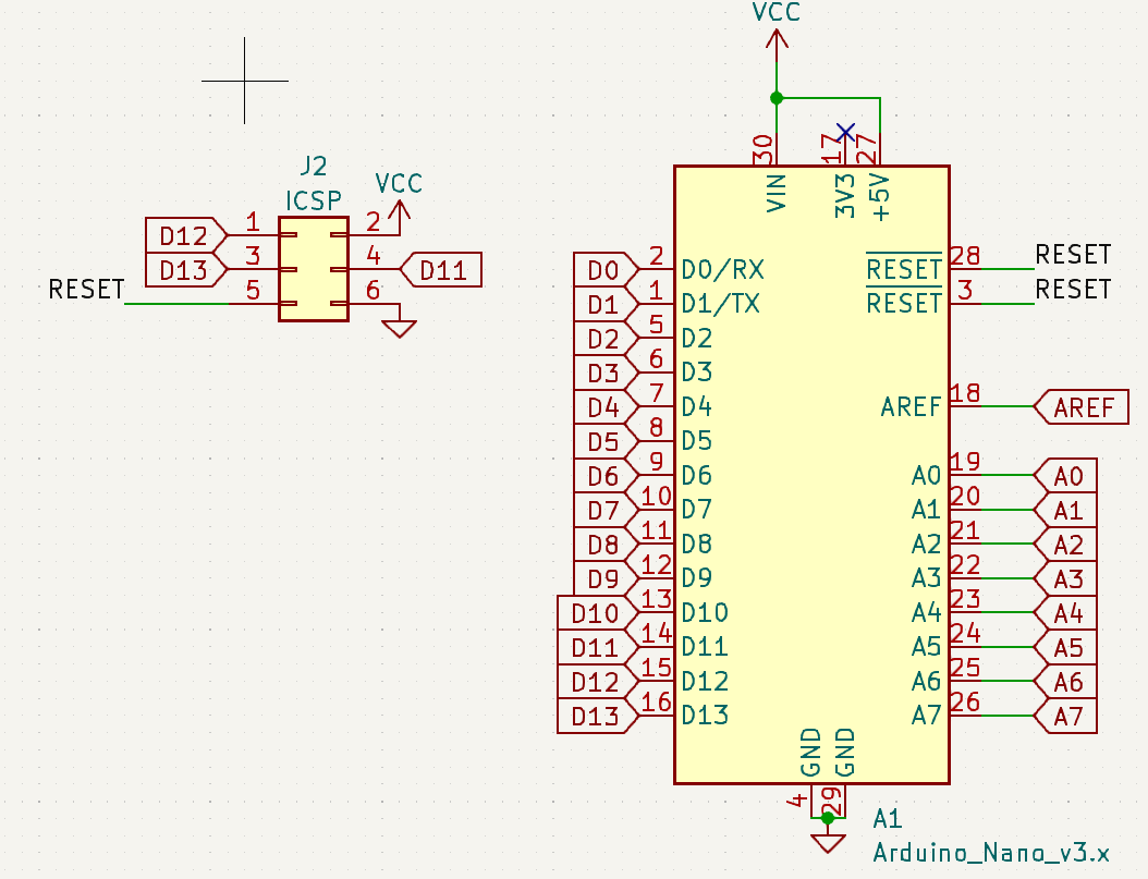
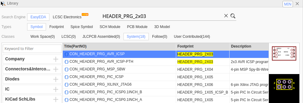
In the Library, under the "System" tab, search for DIP-30 ARDUINONANO and HEADER_PRG_2x03 to find these headers.
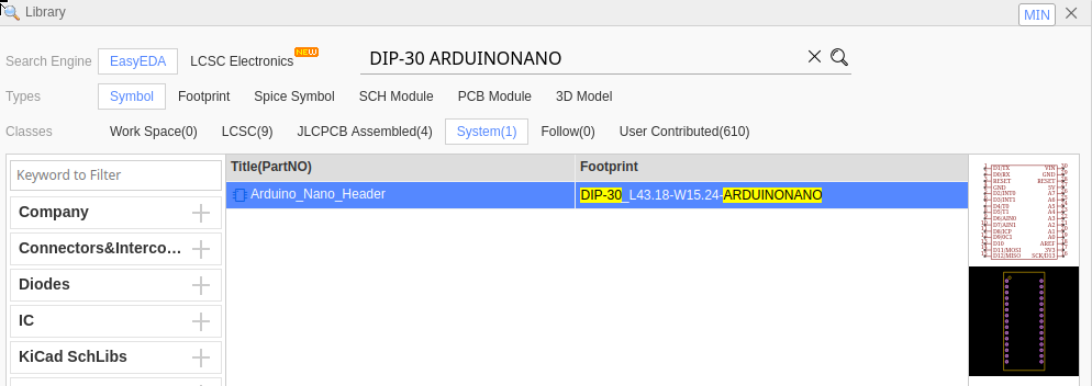
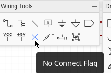
First, we have the traditional Arduino Nano pinout connected to our labels, telling the ECAD software we want these headers connected to the prespecified microcontroller pins. Since this whole board is running at 5V, just mark 3V3 as NC (No Connect).
We also have the ICSP header, which is used for flashing the Arduino's bootloader. It has all the SPI pins in one neat package, MISO, MOSI, SCK, RESET, VCC, GND.
USB
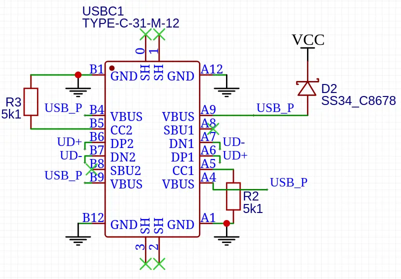
We start with the 16 Pin USB 2.0 Type C receptacle, C165948.
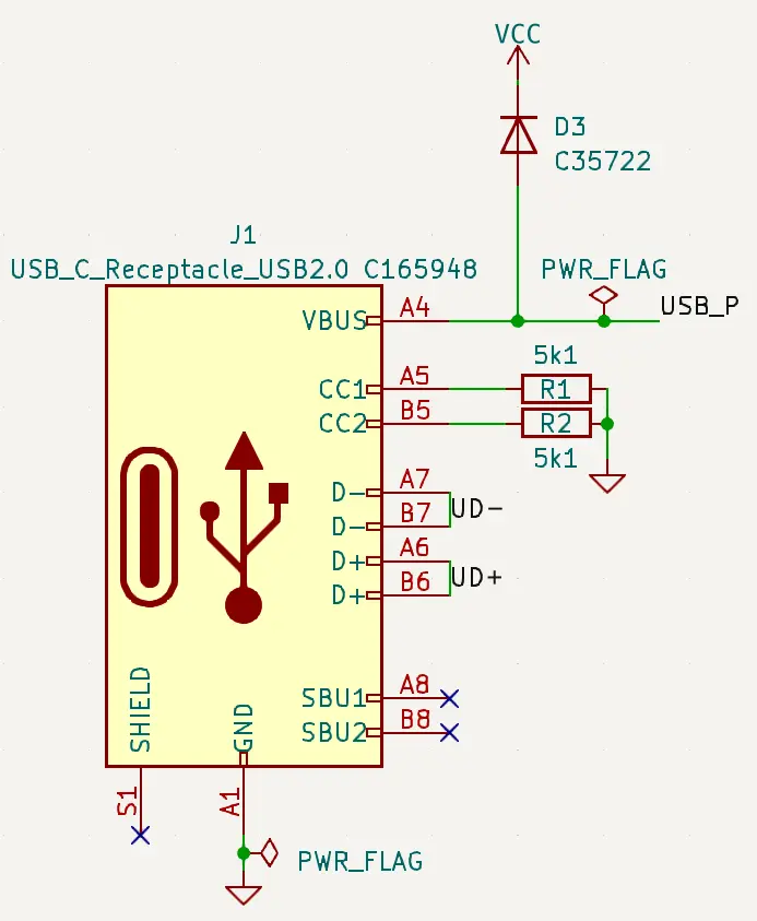
NC: SBU1/2 and Shield/Shell (shield is only for hosts).
GND goes to our ground net.
Mark VBUS with a net, and then run it through a diode to the VCC net, which powers everything else on this board.
Since we will be powering a bunch of LEDs, I picked a big diode JLCPCB had as a basic part, C35722. This diode prevents current from going back into your computer if both USB and 5V pins are plugged in.
Then, to tell the USB-C port that we are drawing power from it, CC1 and CC2 have to each be connected through separate 5.1k resistors to ground. That tells the USB-C power adapter that we can draw up to 5V 3A.
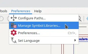
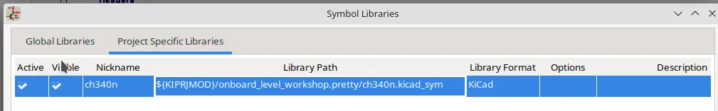
You can download the KiCAD CH340N footprint here: ch340n.kicad_sym. Then, put it in your project folder and add it to your symbol library in Preferences > Manage Symbol Libraries > Project Specific Libraries.
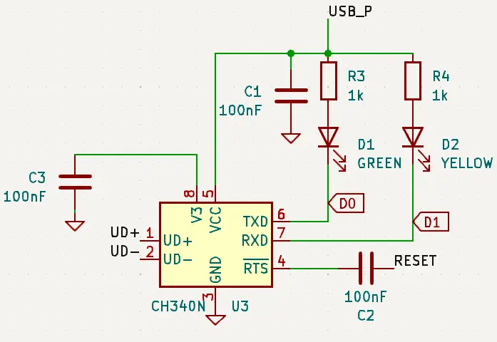
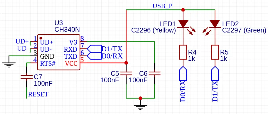
Now, we can connect our UART chip, the CH340N. Both D+ and D- from the USB-C connector go to D+/- on the CH340N. As specified in its datasheet, both V3 and VCC get 100nF decoupling capacitors. RTS goes to RESET through another 100nF capacitor; this capacitor makes the RESET pin briefly pulse low instead of staying low forever (avoiding bootlooping the MCU).
RXD and TXD (USB directionality), are connected to their microcontroller pins D1 (MCU's TX) and D0 (MCU's RX) respectively with some status LEDs.
Done!
Now you have a simple Arduino Nano Compatible Board Schematic! Check out Part 2 to turn this into a PCB, or Part 4 to add more features to this board.


Footnotes
- Thanks to Hugo Hu for his instructable, this is based on that design: https://www.instructables.com/ATmega328P-Corgi-Arduino/
- WARNING: You will need another microcontroller board to flash the bootloader on this ATmega328P before you can program it with USB.