

Join Hack Club Horizons! Ship your projects and fly to your first hackathon →
Have you ever made a die using electronics? This workshop will create a virtual die that displays a random number between 1 and 6. You can use this project for your next board game.
We will learn how the Seven Segment Display Interface for Arduino works.
Here you can find the whole working model.
Setup
We are going to use Tinkercad's interactive circuit builder, which is terrific. It's like building an Arduino circuit in real life. With the expertise you gain from making this circuit online, recreating your circuit with physical components should be a breeze!
Go ahead and create an account in tinkercad

You will be redirected to the Dashboard.
Now click on Create new Circuit.
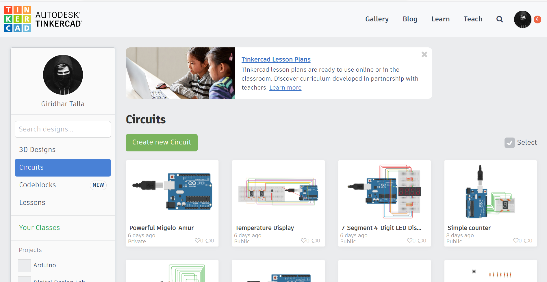
Just click on the name at the top left and rename your project.
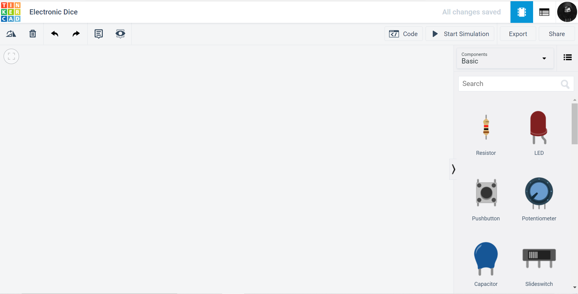
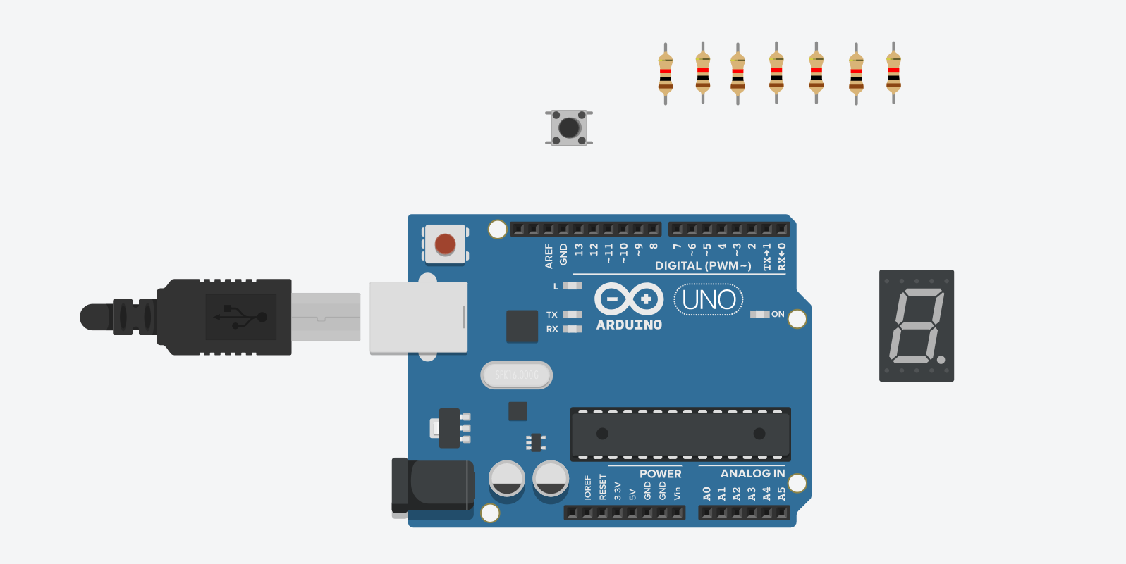
You will see something like this 👇 with all the components on the right side.
After setting up, let's start tinkering.🚀
Components
- Seven Segment Display
- An Arduino UNO board
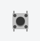
- Push-button
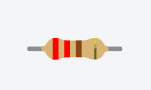
- Resistors
1) Seven Segment Display
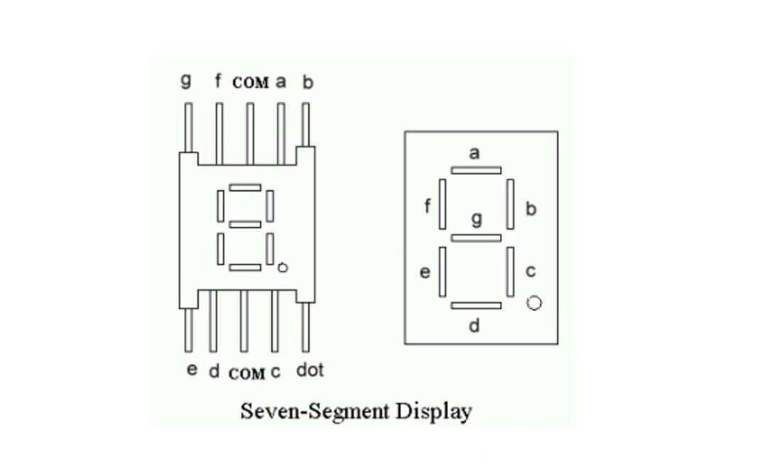
The first part we'll use in our project is a seven segment display. A seven segment display is a simple device. It consists of seven LEDs arranged in segments. Hence, the name Seven Segment Display. Each LED Segment is in the shape of a hexagon, and all the seven LEDs are arranged in an "8" like fashion so that it can display digits 0 to 9.
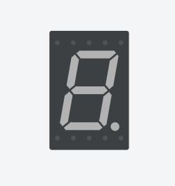
The top five pins are g, f, COM, a, and b, while the bottom five pins are e, d, COM, c, and dp. Since it is a common anode display, the COM (common pin) is connected to the Common Collector Voltage.
Let us first look at the internal structure of a Common Anode Seven Segment Display, i.e., how the LEDs are connected.
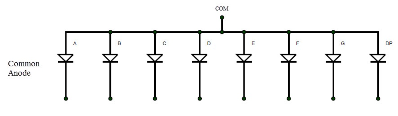
We can observe that the anodes of each individual are connected as one (to positive (+)), and for turning on the LEDs according to the number to be displayed, the respective cathodes are connected to the negative(-) terminal.
To display digits from 0 to 9 on this seven-segment display, you need to activate specific segments for each number. The following table indicates the list of segments you need to turn on to display a particular digit.
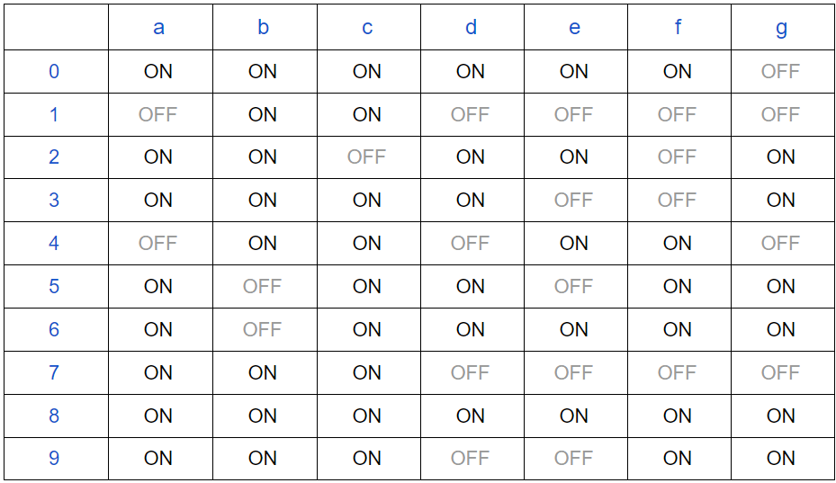
This table helps us while we are programming our Arduino.
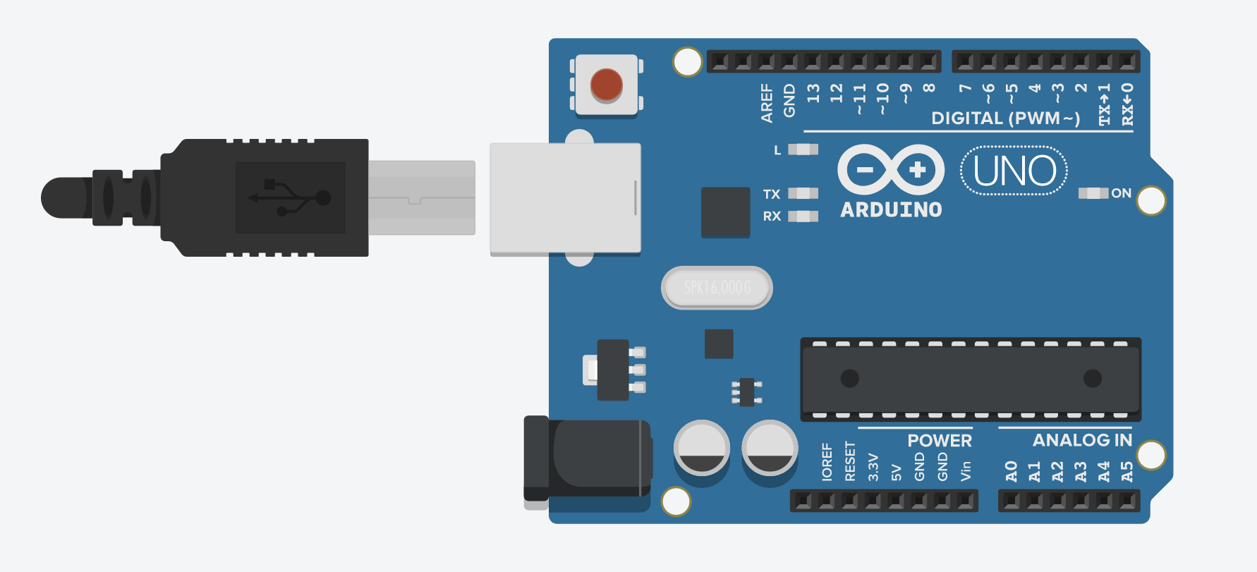
2) An Arduino UNO board
The other part we will use in our project is an Arduino. The Arduino Uno is an open-source microcontroller board based on the Microchip ATmega328P microcontroller.
If you're interested in Arduino, you can learn more from here
3) Push button
We are going to use a push-button, which we'll click when we need to roll a dice. By pressing, we will obtain a random number between 1 and 6.
4) Resistors
In this project, we will use seven resistors having 220ohm resistance.
Building our circuit
You will find the window as it appears like this when you open tinkercad.
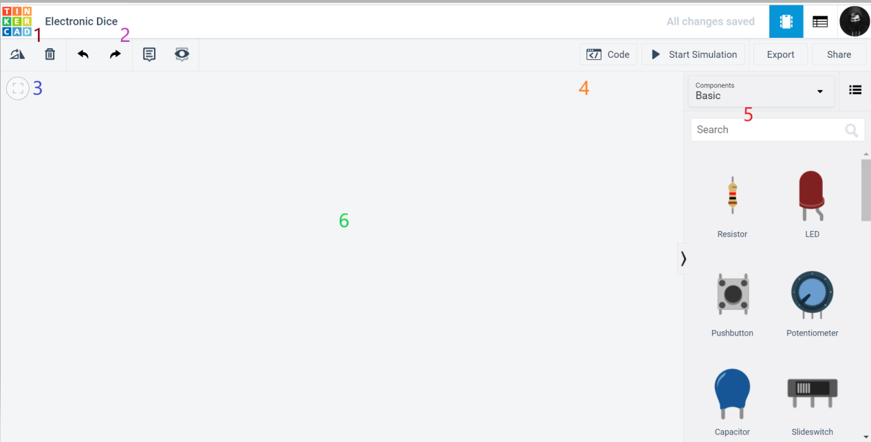
First one: This is the logo of the tinkercad, which we are using now.
Second one: It's the title of the project we will give as Electronic Dice.
Third one: Those are some actions we use to create circuits such as undo/redo, delete, rotate, etc.
Fourth one: the code window button, the button for starting the simulation, and options to export and share your model.
Fifth one: On this window, you will find a wide variety of all components required for not only this but for any other projects; you can easily drag and drop them into your workspace.
Sixth one: Finally, this is the workspace window onto which you will drag and drop the components needed and connect them.
First, select the components from basic to all; by default, it will be chosen as basic.
Let us start with dragging the Arduino board.
The next component is our seven segment display. You can get it by typing the name in the search box provided. After finding it, just drag it from there to the workspace and place it beside the Arduino board. Also, drag a push-button and 7 resistors onto the screen. You will find them just by typing the name in the search box. Drag it and place it on the workspace.
So far, our workspace will be looking like this.
Wow! you are doing great.
The resistance of each resistor will be 1 Kohm by default but need only 220 ohms of resistance. Let us see how to set the resistance of the resistor to 220 ohms.
After collecting all the seven resistors, click on each of the seven resistors, and you will find the dialogue box, which appears as shown below.
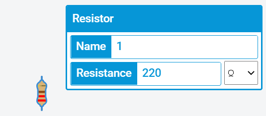
In the Resistance tab, you can set the resistance value of your own, and the tab next to it is the unit, which is a dropdown used to set the resistance unit.
Now set the resistance value to 220 and the resistance unit in the dropdown as plain ohm. Now you are set for one of the seven resistors. Now repeat the same thing to all the other 6 resistors and set the resistance value to 220 ohms.
The name field which appears when you select a component is ignorable. They are just for labeling purposes.
Excellent! You are all set with the components needed for our project.
Yes, the time has come to proceed further and give connections for our circuit.
Wiring the circuit.
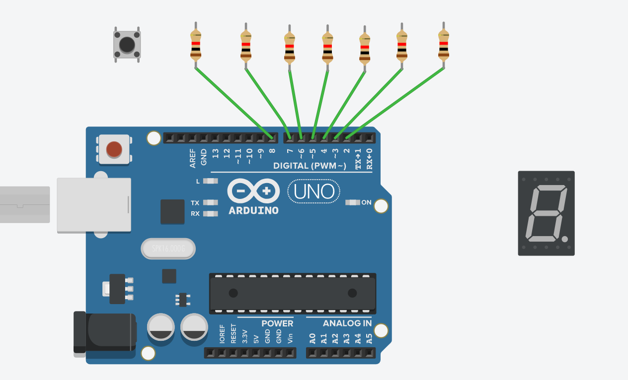
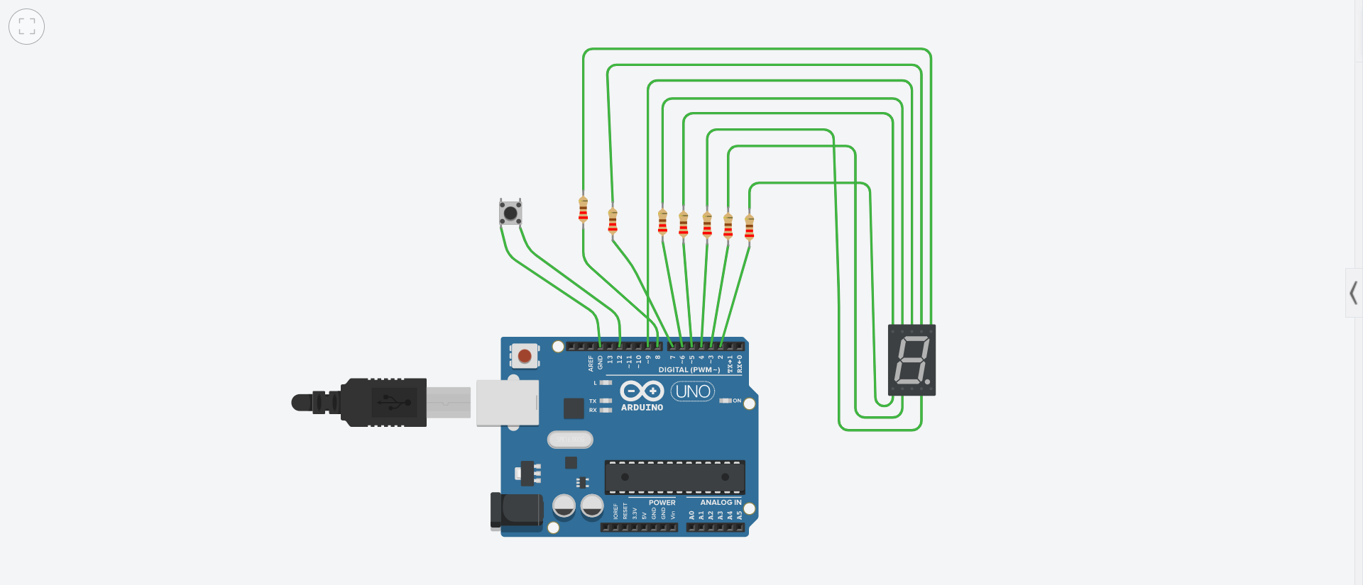
Place the seven resistors of 220-ohm resistance on the top of the digital side of the Arduino board. Each of the 7 resistors should be placed on the top of PIN 8, 7, 6, 5, 4, 3, 2 one by one.
Of the two ports which the resistor has, the port which is facing the Arduino Uno board is used to connect to the respective PIN. When you select the resistor's port, you will be seeing that a wire of green color is being created.
Drag the wire from the end of the resistor to the respective pin and drop it there. Now you will see the connection is established between the resistor and the Arduino UNO board. Repeat the same thing to all the other six resistors, and directly the seven resistors are connected to the Arduino UNO board.
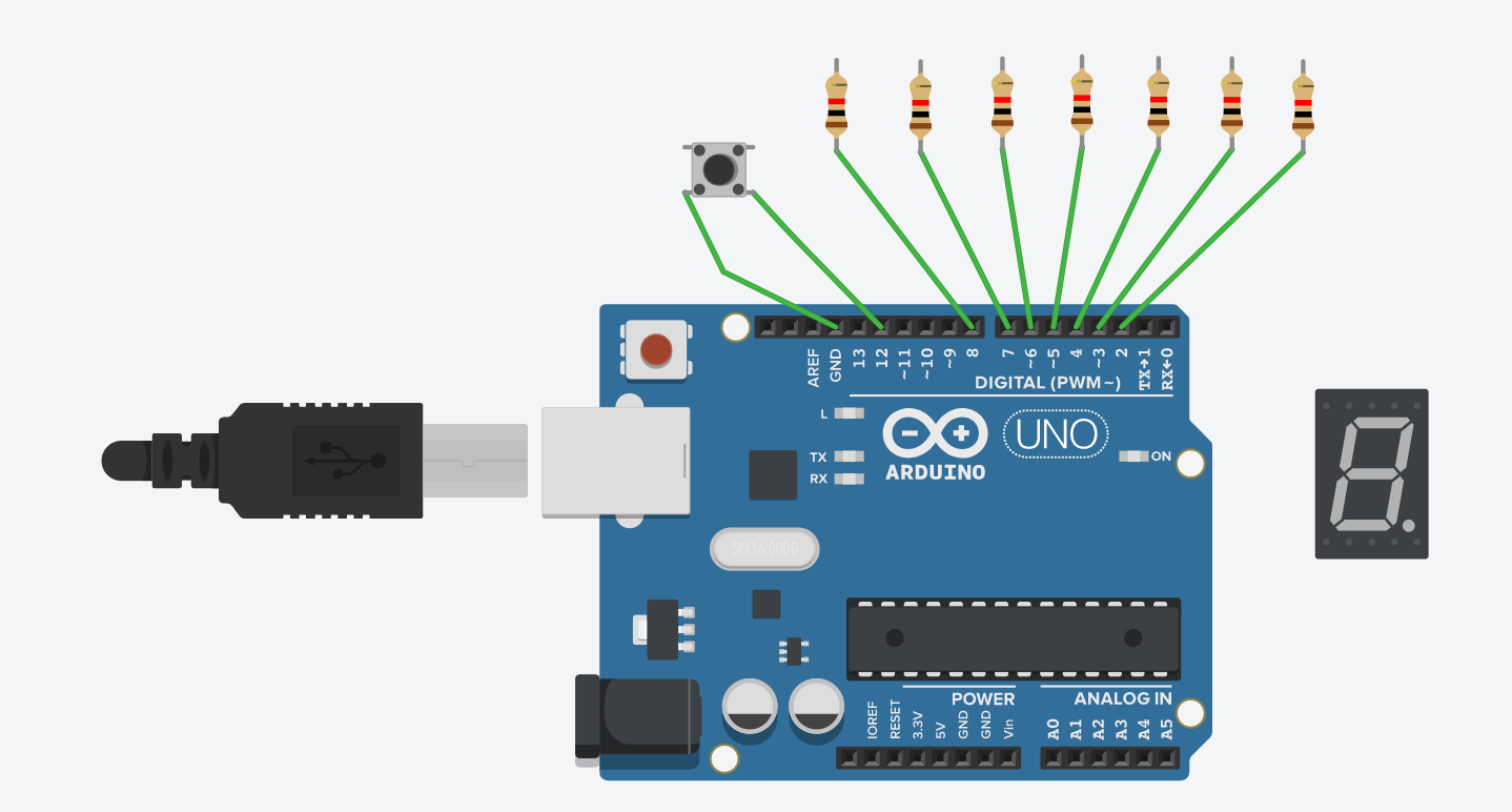
Connect terminal 1a of the push button to the ground, which is represented as gnd on the digital side of the Arduino. Next, connect the terminal 2a to PIN 12 of the Arduino in the same way.
Now the time has come to connect the seven segment display to the Arduino board. You will find the seven segment display port number when you take your mouse pointer near the respective port. To begin, connect the g port of the seven segment display to the other end port of the resistor, connected to the 5 pin of Arduino.
Similarly, connect the port f of segment display to 6 pin of Arduino, a to 7, b to 8.
Connect the upper side common port to the 9 pin of the Arduino board directly without any resistor.
Now coming to the lower side of the seven-segment display. In the same way, you connected the upper portion of the seven-segment display connects the lower ports c to 4, d to 3, e to 2. The connections of the seven-segment display registers and Arduino board are completed now. Leave the common port and DP port on the lower side of the seven-segment display.
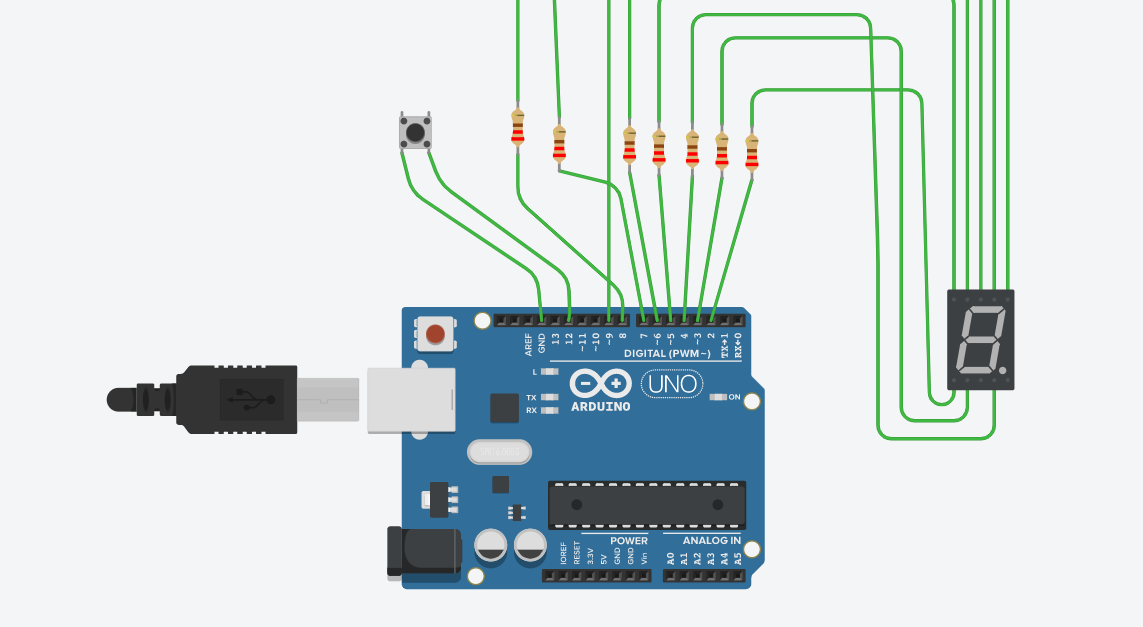
The final circuit, after all the connections, looks like this.
Yay! All the connections are set, and we are free to proceed further to code the Arduino.

Coding our Arduino.
As we saw earlier, the code button was at the right side top corner of our tinkercad. Click on that and toggle from block code to text code.
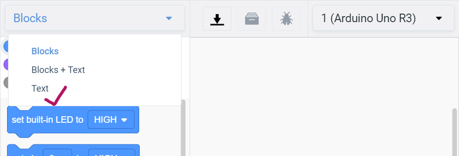
We are now set to start coding. By default, in the code window, there will be some code written on it. Go ahead and delete everything in the window. Let's start coding, which our circuit requires.
As we saw in the table earlier, this code written at the bottom is based on that one. 1 means ON and 0 means OFF.
int num[10][7]= {
  {0,0,0,1,0,0,0},
  {1,1,0,1,1,1,0},
  {0,0,1,0,1,0,0},
  {1,0,0,0,1,0,0},
  {1,1,0,0,0,1,0},
  {1,0,0,0,0,0,1},
  {0,0,0,0,0,1,1},
  {1,1,0,1,1,0,0},
  {0,0,0,0,0,0,0},
  {1,0,0,0,0,0,0}
};
The LEDs are arranged in an "8" shape, and to display a digit, individual LEDs should be turned on and turned off. This block of code does the thing we wanted to.
Now define some variables we need:
r_num: random numberroll: the pin we use for rolling the dicestate: state of PIN 12
long r_num;
int roll = 12;
bool state = true;
Under this block of code, the main parts are considered the head and body of our code.
void setup()
{

}
void loop()
{

}
The setup() function will only run once, after each powerup or reset of the Arduino board. This function is called when a sketch starts.
After creating a setup() function, which initializes and sets the initial values, the loop() function does as its name suggests, loops some hundreds of times consecutively if required, allowing your program to change and respond. It repeatedly loops until the program either crashes or decidedly ends.
The void thing we wrote is a return type, i.e., if our code block does not require any value to return rather than just printing something or initializing or giving values. You can learn more here
Now coming to the first loop, i.e., setup(), first of all, we are going to tell Arduino which pins are we using, and the other one is to give commands of the pins which are connected to either any of the components, i.e., what should the pin connected have to do.
void setup()
{
  pinMode(2,OUTPUT);
  pinMode(3,OUTPUT);
  pinMode(4,OUTPUT);
  pinMode(5,OUTPUT);
  pinMode(6,OUTPUT);
  pinMode(7,OUTPUT);
  pinMode(8,OUTPUT);
  pinMode(9,OUTPUT);
  pinMode(12,INPUT_PULLUP);

  digitalWrite(2,HIGH);
  digitalWrite(3,HIGH);
  digitalWrite(4,HIGH);
  digitalWrite(5,HIGH);
  digitalWrite(6,HIGH);
  digitalWrite(7,HIGH);
  digitalWrite(8,HIGH);
  digitalWrite(9,HIGH);

  randomSeed(analogRead(0));

}
The function used to tell the Arduino which pin we will use is pinMode(pin number, OUTPUT/INPUT). As in our circuit, we used 2 to 9 pins. We will declare them as above and as they are all giving output mentioned as OUTPUT.
The INPUT_PULLUP is written to enable the internal pull-up resistor.
The next command we used is digitalWrite(pin number, HIGH/LOW). If the pin has been configured as an OUTPUT with pinMode(), its voltage will be set to the corresponding value: 5V for HIGH, 0V (ground) for LOW.
randomSeed() initializes the pseudo-random number generator, causing it to start at an arbitrary point in its random sequence.
You can find furthermore reference here.
The next block of code is written in loop().
Add the following code:
void setup()
{
  if(state)
 {
   r_num = random(1,7);
   for(int i=0;i<7;i++)
    {
      digitalWrite(i+2,num[r_num][i]);
    }
    state=false;
 }
}
If the state is true, we will display a random number. The random(1,7) shows a random number between 1 and 6. Using the for loop, we will make the required pins ON to display a number. Then we toggle the state to false to avoid a forever loop.
Now you can see every time you start the simulation, you get a random number displayed.
Let's add functionality to our button. When the button is clicked, we have to display a random number after toggling some numbers.
Add the following code:
void setup()
{
  // previous code
  while(digitalRead(roll)==LOW)
  {
    for(int i=0;i<10;i++)
      {
      for(int j=0;j<7;j++)
        {
          digitalWrite(j+2,num[i][j]);
        }
      delay(50);
      }
  state=true;
  }
}
When the push button is pressed, numbers from 0 to 9 toggles. For this, we use two for loops to iterate through the num matrix. Toggling will be very fast. So we add delay of 50 milliseconds.
We turn the state to true for displaying a single random number.
Hit the run simulation button.
Nice! We're all set!
Here's the final code:
int num[10][7] = {
  {0,0,0,1,0,0,0},
  {1,1,0,1,1,1,0},
  {0,0,1,0,1,0,0},
  {1,0,0,0,1,0,0},
  {1,1,0,0,0,1,0},
  {1,0,0,0,0,0,1},
  {0,0,0,0,0,1,1},
  {1,1,0,1,1,0,0},
  {0,0,0,0,0,0,0},
  {1,0,0,0,0,0,0}
};

long r_num;
int roll = 12;
bool state = true;

void setup()
{
  pinMode(2,OUTPUT);
  pinMode(3,OUTPUT);
  pinMode(4,OUTPUT);
  pinMode(5,OUTPUT);
  pinMode(6,OUTPUT);
  pinMode(7,OUTPUT);
  pinMode(8,OUTPUT);
  pinMode(9,OUTPUT);
  pinMode(12,INPUT_PULLUP);

  digitalWrite(2,HIGH);
  digitalWrite(3,HIGH);
  digitalWrite(4,HIGH);
  digitalWrite(5,HIGH);
  digitalWrite(6,HIGH);
  digitalWrite(7,HIGH);
  digitalWrite(8,HIGH);

  digitalWrite(9,HIGH);

  randomSeed(analogRead(0));

}

void loop()
{
  if(state)
  {
    r_num=random(1,6);
    for(int i=0;i<7;i++)
    {
      digitalWrite(i+2,num[r_num][i]);
    }
      //delay(1500);
    state=false;
  }

  while(digitalRead(roll)==LOW)
  {
    for(int i=0;i<10;i++)
    {
      for(int j=0;j<7;j++)
        {
          digitalWrite(j+2,num[i][j]);
        }
      delay(50);
    }
  state=true;
  }
}
Now you will find a random number being displayed whenever you press the push button (i.e., rolling a die).

Next Steps
Now that you know about Seven segment display, go wild with it! Here are some other projects to inspire you:
PS: I'm @Giridhar on Slack!